NIFS Two Colour Interferometer
We have designed and built for National Institute for Fusion Science, Nagoya, Japan a two colour interferometer to measure electron line density in their new Large Helical Device [LHD].
The design measured the first plasma within the LHS vessel on the 31st March 1998, proving that the machine construction was completed on time.
The design following a similar instrument used for the divertor line density measurement at JET near Oxford in the UK. Probing at both 140 and 285 GHz the NIFS instrument allows the mechanical movement of the machine, caused by the large forces as changing currents and mangnetic fields interact with one another, to be deconvolved from the change in electron line density as the pulse progresses.
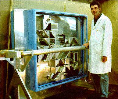
Here is Professor Kawahata-san of NIFS and Richard Wylde next to the Interferometer
The complex plasma form is inside the vessel is well captured by this internal 'photo:
This is an example of the phase change measured by the instrument at 1GHz when a wedge of HDPE was introduced into the plasma arm and then more slowly removed. The phase change agreed very well with the prediced value based on a HDPE Refractive index of 1.52.
And here are a couple of views of the instrument. First the Transmit side.
and the Receive side:
Instrument maker Trevor Walker in front of the Quasi-Optics structure.
HE11 guides are used to transport the two probing frequencies - 140 and 285 GHz - to the LHD and back. Compared with smooth rectangular guide, overmoded HE11 guide has very low loss and maintains polarization purity. It has the added advantage over smooth guide that it couples well to the free space Gaussian beam modes found within our Quasi-Optics.
The photograph below shows a flat mirror diverting the beam into the HE11 guide.

It is necessary that the the two colours have the same polarisation as they probe the beam. To do this the signals are overlaid in the same polarization by a Martin Puplett diplexer on the transmit side and recovered into two channels by an identical MP on the receive side of the instrument. Adjustment of the Martin-Puplett diplexer path length allows the prtobing polarisation to be horizontal or vertical.
Corrugated feed horns, such as the one seen here, convert signals from the sources and mixers into free space beams. Off-axis ellipsoidal mirrors control the beam expansion

Both the transmit and receive sides of the Instrument, found on each side of a thick Aluminium plate, are fully inclosed in a RAM lined box. This, along with other techniques, including the uses of free space Faraday rotation isolators insures that the main received detecting signals returning from the LHD, and not leakage from the source which as not passed through the plasma .

To achieve the accuracy desired by NIFS, we have provided a Dynamic range of 70dB or greater. (By dynamic range we mean that the signal enterimng the HE11 guide could suffer 70dB of attenuation and still give a Signal/Noise ratio of 1.) To achieve this demanding task, solid state sources are used which are phase locked and Schottky mixers employed to detect the returning signal. By careful design and accurate manufacture the Quasi-optics losses can be made essentially negligible.