Quasi-Optical Faraday-rotation-based Isolators
New developments give Insertion losses below 0.4dB and Isolations >40 dB around 100 GHz, and operationally useful results at 240 and 300 GHz.
A detailed paper on the design of high frequency circulators and Isolators - published Trans MTT
For example, UCSB use a double isolator system to lock their FEL at 240 GHz
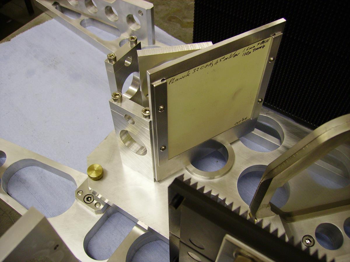
ESTEC are using a 310 GHz isolator which forms part of a TK supplied illuminator for the calibration of the ESA Planck CMB mission
Our QO isolators use a 45 degree impedance-matched Faraday rotator to rotate the plane of polarization of a beam (in this example) going from right to left from 45 degrees to horizontal, In this polarization state the beam can pass without loss though the second vertical degree grid. A beam heading the other way suffers rotation in the same sense and is dumped into the absorber after passing though the Faraday rotator. Our rotators are based upon magnetically hard ferrite material and do not require external magnets.
Such Faraday rotators are core components in many Quasi Optical systems, allowing the construction of Isolators, Circulators and Multiplexers, paralleling what is available in waveguides at lower frequencies. Although waveguide based isolators are available at 94 GHz, they do not have this level of performance and this performance advantage only grows as the frequency is increased.
Recent developments in modelling the complex permeabitity and permeativity of new ferrite materials, using a Mathematica-based ABCD matrix approach:
Section of Mathematica code, used to model Isolator performance:

Here we show modelling of predicted isolation, in dB, for a 94 GHz isolator.
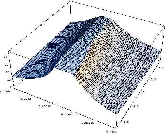
Isolation as a function of blooming layer thickness (LHS) and permeativity (RHS)
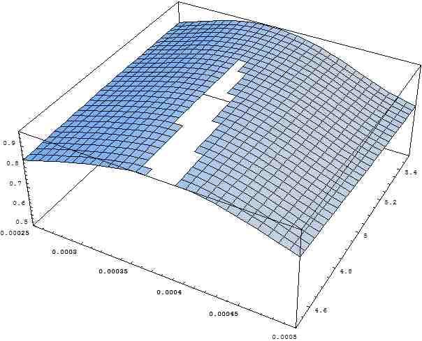
Insertion loss as a function of blooming layer thickness (LHS) and permeativity (RHS).
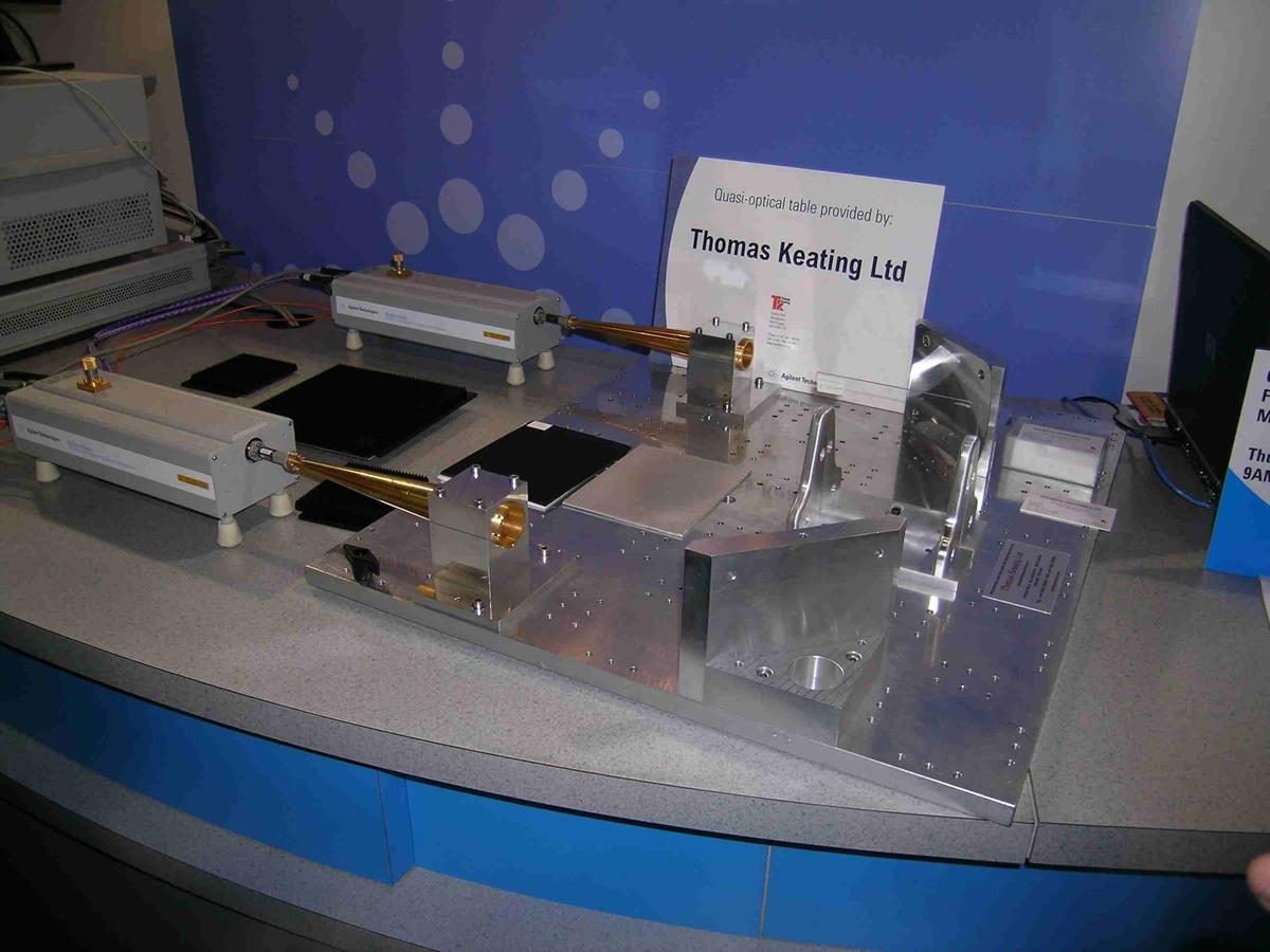
Maesurement work - conducted during 2005 - is now showing fruit, as indicated from the following measurements, made on a TK QO bench coupled with Agilent PNA:
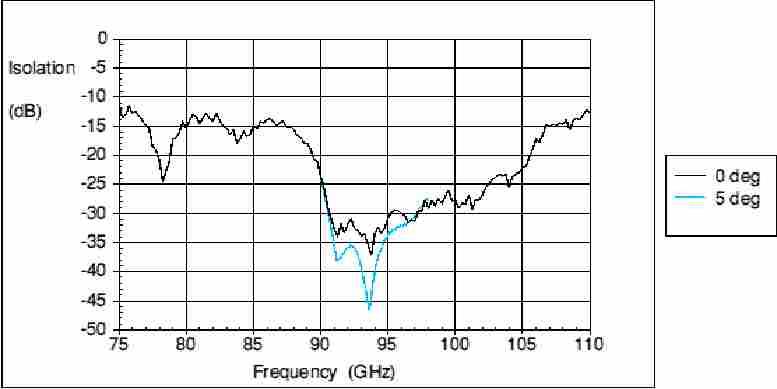
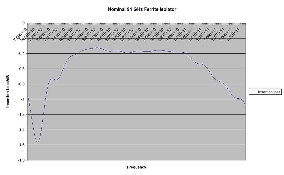
The performance of an isolator measured on this equipment is given below, with >30dB isolation over a 10% bandwidth.

and insertion loss < 0.4dB (ie more than 90% transmission) over a 15% bandwidth.
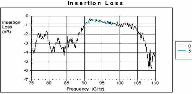
Modelling of Isolators working at higher frequencies give hope that the combination of these advanced modelling techniques and new materials will give good insertion loss - well below one
dB - at frequencies in the 250 GHz region. Older results measured as part of the testing our our two colour NIFS interferometer in the late 1990's show insertion losses of 0.9dB and
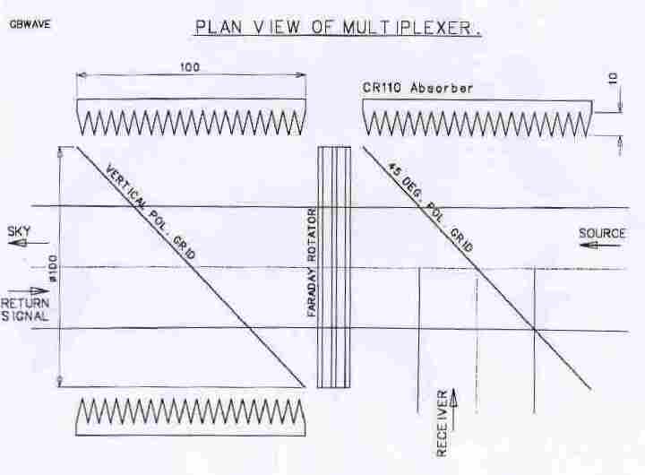
isolation of 24.4dB at 140 GHz and insertion losses of 2.24 dB and isolaton of >30dB at 285 GHz.Such a device can act as a multiplexer or circulator: In this schematic, for a
Cloud Radar application, source power is set to the Sky and returing power routed to the Receiver.
Just such a multiplexer, operating at 94.05 GHz and designed to handle more than 1.5KW (2% duty cycle), has been built and tested by TK, giving insertion losses at the 0.5dB level and
isolation >35dB.