Quasi-Optical Measurement Circuit for Agilent's VNA's
Thomas Keating has long been associated with Quasi-Optical Measurement systems. Here we
present a simple free-space measurement system, which when combined with the current generation
of Agilent's VNA's and analysis software provides a powerful measurement tool for the determination
of complex material properties.
QUASI-OPTICAL MEASUREMENT SYSTEM
By Quasi-Optics, we mean optics where the sizes of the optical components is small with respect to the
wavelength, and that one has to use geometrical optics to design such systems.
Gaussian beam-mode optics is the appropriate tool to design such circuits. The Agilent VNA hardware
is a "zero gain" circuit whereby a Gaussian beam waist at the aperture of a corrugated feed horn
(Port S1) is refocused by an ellipisolidal mirror to form a beamwaist at the sample position and then
is passed, via a second mirror, to the S2 Port, where a second corrugated feed horn feed the beam
into the VNA waveguide.
Corrugated feed horns are used here because they produce axially symmetrical beams with low side lobes.
We can use Gaussian beam mode analysis to predict the form of the beam passing though the circuit:
At 94 GHz, the circuit shown below gives a value of just under 25mm for the beamwaist at the sample
position (We use the 1/e amplitude level as the definition of beamwaist - the power level has dropped
to -8.6 dB).
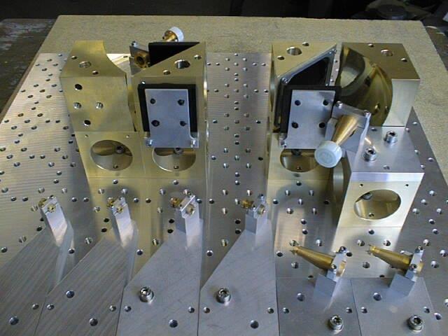
We use mirrors in our quasi-optical circuits to control the expansions of the Gauissian beams. They are
prefered over lenses, having wider bandwidth, very low (basically not measureable) absorption loss. They
do generate, however - when used off-axis - higher order and X-polar modes. We choose the focal lengths
of mirrors in our QO circuits to keep these higher order and X-polar mode conversions very low.
The size of the beamwaist at the sample is chose to be large enough that the sample is being probed by
a plane wave. In the case shown below, the waist is 25mm in size and is associated with plane waves over
a characteristic spread of angles of about 2.3 degrees.
(via the Gaussian Beam mode divergence formula: Theta = Lambda/Pi Wo, Theta being in radians).
It is obviously important that the power at the edges of the beam do not suffer from truncation. The
circuit is built on a cube system - where the cube size is 125mm per side. At the sample holder, the
clear aperture is >100mm and edge truncation levels therefore (because the beam is very close to
being a pure Gaussian) at the -35dB level. This rises slightly at the long wavelength end of operation
(30mm at 75 GHz) dropping to smaller value (22mm at 110 GHz) at the edge of the upper band.
It is important that the sample size and beam landing on it be large enough so that derivations of
material properties based upon standard plane wave analysis are valid to the tolerance required.
A couple of notes on the required beam size written by Dr. Graham Bell can be downloaded here:
and here
Losses in well designed QO systems can be very low: In this case losses in the whole circuit, from
S1waveguide to the S2 waveguide port (passing though two corrugated horns, two mirrors and free
space inbetween) is around the 1 to 2dB level.
Gaussian Beam mode analysis of the beam passing through the QO Measurement Sysyem
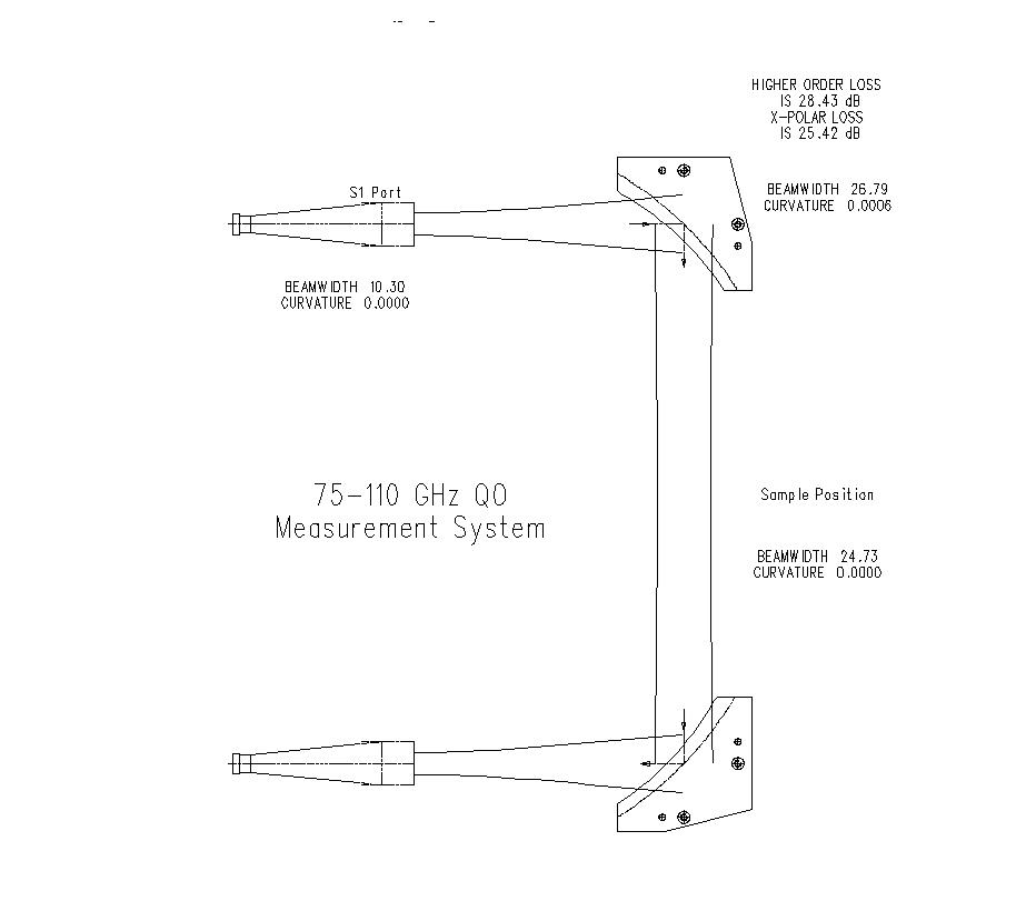
The beams shown in this picture at the the 1/e amplitude level
Systems can be build for operation in Automotive Radar frequencies -Here around 78 GHz

And a 3-D view of the beams:

which have a very respectable 0.6dB S21 (and S12) transmission loss at centreband. Here are bandsweep measurements taken with
our instrument in Germany using an Agilent E8363B PNA with 60-90 GHz heads

Here are S11 and S22 measurements, giving horn losses - by placing a mental reflector across the horn aperture.
![]()
Frequency Range of QO Measurement systems
Thomas Keating has built QO systems to operate over a very wide range of frequencies. Here is a system operating down to 3 GHz
which show signiicant advantages of QO benches in material measurements over standard NRL Bridges - see a
comparison of comparisons of both methods, kindly provide by Peter Lederer at Quinetiq: the QO results are much
more stable.

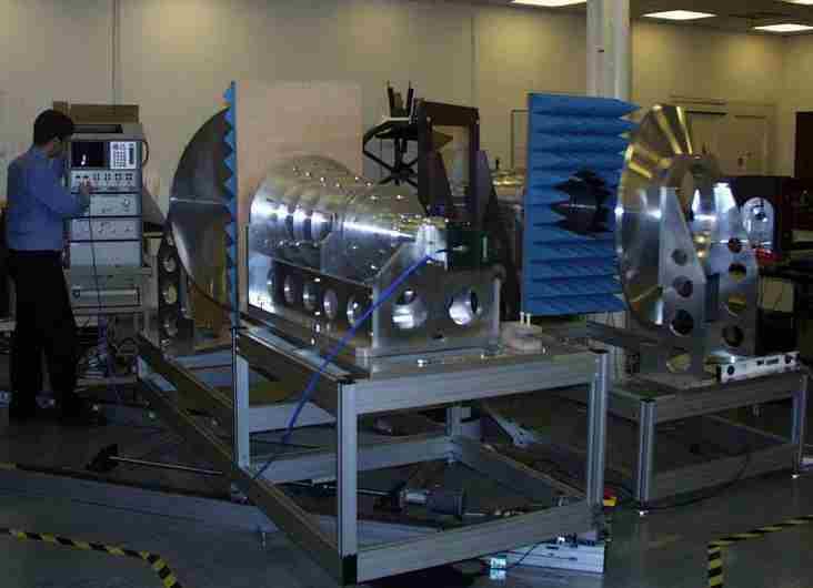
and here are components of as system for making measurements above 600 GHz
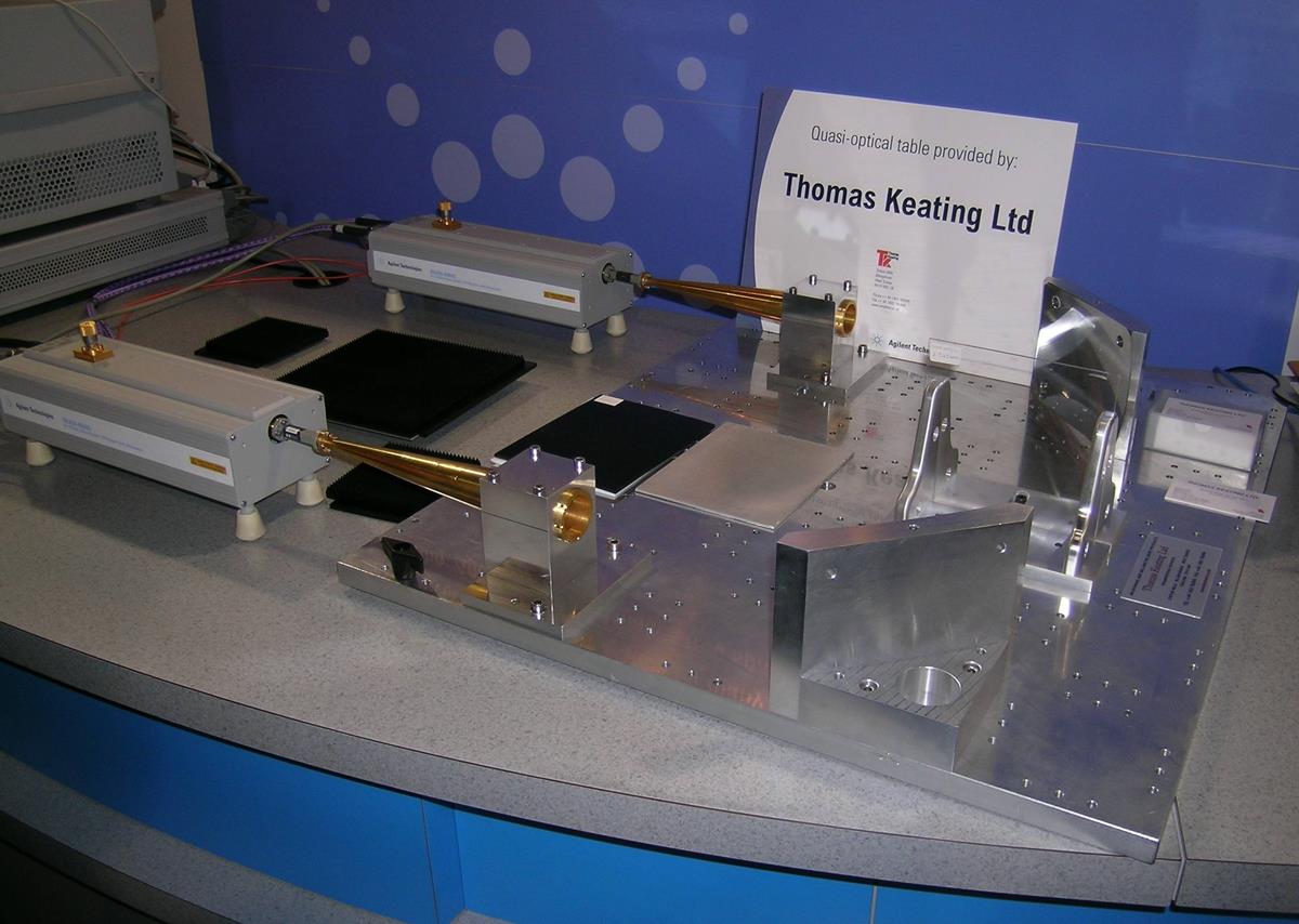
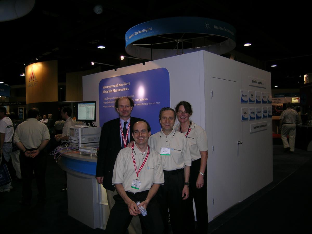
The QO system at the IEEE's annual MTT exhibition - here at Long Beach, CA in June 2005
In passing....
here is a short video showing a QO bench designed to measure hot materials, built for a US corporation
Richard Wylde - Thomas Keating Ltd -